Warm stone and graphite. A quiet single status light. A removable top without visible face screws. Created from native CAD around the actual Rev G assembly—not an illustrative replacement for the hardware.
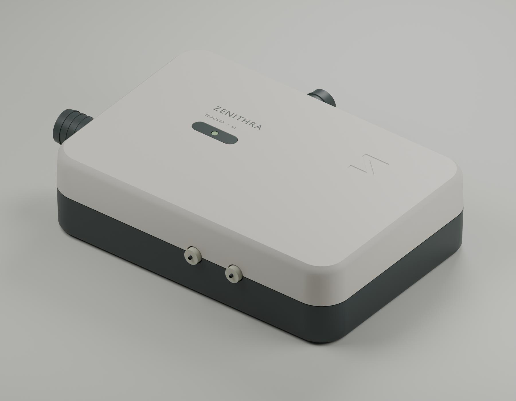
No physical unit has been built or tested. Mechanical H has not been sent to JLCPCB and does not modify the frozen Rev G board or its quotation. Enclosure tooling and commercial release remain on hold.
The enclosure moves from 126 × 84 × 32.4 to 132 × 90 × 33.6 mm (34.8 mm with feet), excluding external cables and antenna connections. The extra perimeter allows 12 mm rounded corners, a more deliberate seam and easier service interfaces. This is a refined enclosure around the existing board, not a miniaturized electronics redesign.
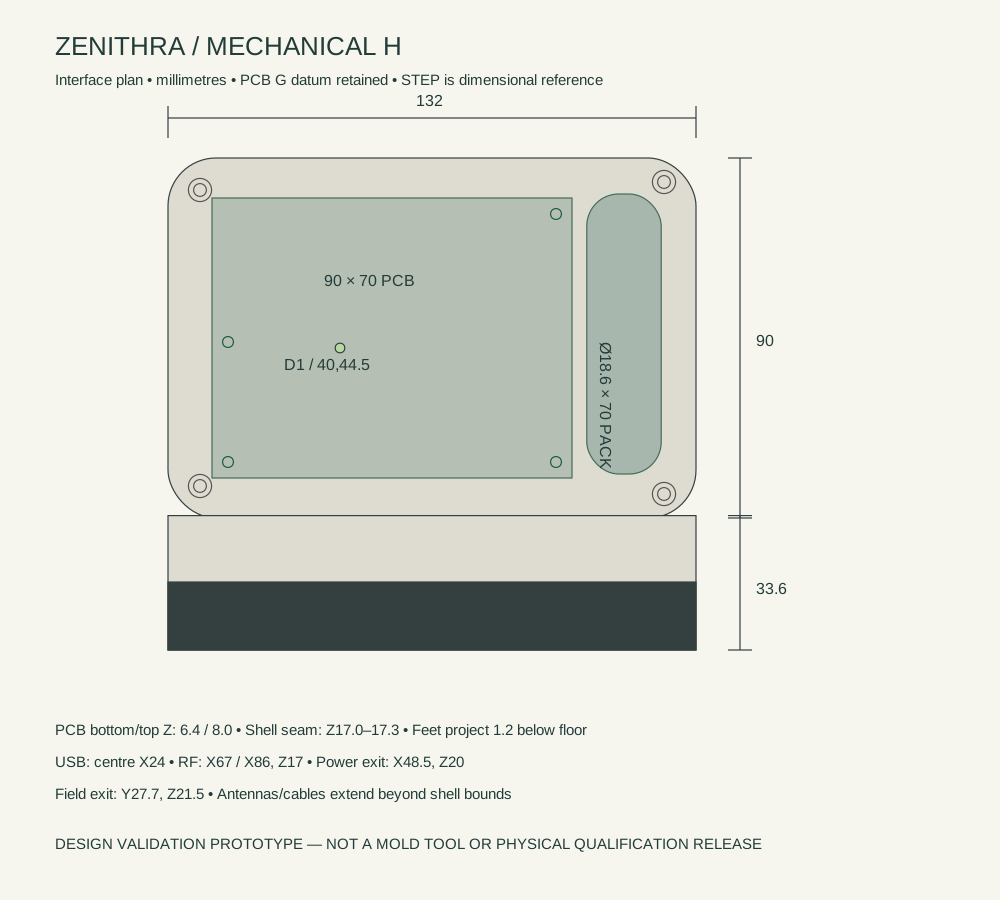
USB acceptance gauge: a 14 × 7.5 mm overmold through the opening, with a 28 mm insertion envelope. Supplier plug length and actual metal engagement are not established by that test. Antennas remain external; no internal antenna or new LED array is implied.
STEP and FCStd use millimetres and assembled coordinates. Each STL is translated vertically so its lowest point is Z0 while retaining X/Y and orientation. Do not independently rescale or auto-centre parts for assembly. The upper-shell STL includes long underside pillars; rotate/support it deliberately in the slicer. PA12 additive prototypes are preferred for fit review; ASA/PETG FDM is suitable for early coupons, with its own tolerance compensation. Optical, elastomer, foot and strap meshes require their specified materials; do not print all parts in one rigid resin and assume equivalent function. Source generators require the parent tracker project plus installed FreeCAD/Blender.
The two rigid shells total 82.80 cm³, versus 80.07 cm³ previously: 3.4% more CAD polymer volume. At an assumed 1.12 g/cm³ density this is approximately 92.7 g, excluding all hardware, inserts and electronics. This is a geometry-based mass estimate, not a material certificate or measured weight.
Cost controls: only two main rigid shells; molded-in colors; die-cut decoration and feet; external antennas retained; no electronics tooling respin; optional mounting plate sold separately. The same shell design accepts either selected color without new geometry. Printed elastomers and an optical prototype precede any dedicated soft-part tooling. Obtain additive and molded quotes before committing tooling at 1,000 units.
No new supplier quote has been obtained. Every $1,000 of tooling adds $1 per device at a 1,000-unit run. Enter supplier figures below; nothing is prefilled as an alleged quotation. Freight, tax, scrap, packaging and warranty are excluded.
Enter supplier costs to calculate.
| ID | Part | Qty | Material/process intent | Constraint |
|---|---|---|---|---|
| H-01 | Lower_shell | 1 | PC/ABS graphite; prototype PA12/ASA | Molded-in color; no coating |
| H-02 | Upper_shell | 1 | PC/ABS warm stone; prototype PA12/ASA | Fine matte texture; no metal near antenna |
| H-03 | Status_pipe | 1 | Clear PMMA optical part | Machined/printed optical prototype; supplier optical grade |
| H-04 | Status_bezel | 1 | 0.5 mm black PET applique | Die-cut/laser-cut; adhesive compatibility to approve |
| H-05 | Field_boot | 1 | TPU prototype; elastomer production candidate | 11.4 mm clear core; supplier must size actual jacket; tie anchor carries pull |
| H-06 | Power_boot | 1 | TPU prototype; elastomer production candidate | 8.8 mm clear core; bounded route plus internal tie anchor |
| H-07 | USB_bezel | 1 | Replaceable elastomer insert | 16 x 9.8 mm aperture; not sealed |
| H-08 | Foot | 4 | Adhesive-backed silicone/EPDM | 11.6 x 5.6 x 1.6 mm envelope; 1.2 mm projection |
| H-09 | Battery_strap | 2 | 4 mm insulating removable strap | CAD is a loop envelope; closure and retention must be selected |
| H-10 | Case screw | 4 | M2.5 x 10 thread-forming candidate | 3.2 mm clearance / 5.8 mm counterbore; pilot and torque supplier approval |
| H-11 | PCB screw | 4 | M2.5 x 6 thread-forming candidate | 2.0 mm blind pilot; remaining floor 1.4 mm |
| H-12 | Cable tie | 2 | Nylon 2.5 mm width candidate | Pass through modeled anchors; qualify on sleeved/jacketed bundles |
| H-13 | Mounting_plate | 1 | Optional PA12 / molded polymer | 156 x 56 x 2.4 mm; external mounting ears |
| H-14 | Bracket screw | 2 | Optional M3 x 8 countersunk thread-forming candidate | Blind pilot; head profile and strip/pull strength require approval |
25 geometry gates + 16 independent export gates passed; zero failed. New mechanical solids were compared against all original component, plug and wire solids: 2,688 pairs. Also checked: 91 new-part pairs; pack growth up to +0.5 mm diameter/length; eight shell registration cases; four intermediate cap lifts; a USB insertion gauge; actual LED air gap; revised power and battery paths, their mutual separation and battery bend-radius bounds. Registration samples ±0.2 mm XY and 0/+0.2 mm above the hard stop; it is not a statistical tolerance analysis.
All native assembly solids are valid. Every manufactured-part STEP/STL round trip is valid, STL-closed, within 1% volume of STEP and based at Z0 for printing. The PCB hash is unchanged. The source check logs record early failures and subsequent fixes. Browser meshes are approximations; STEP is the reference. No structural FEA, mold-flow analysis, optical simulation or new enclosed thermal/RF qualification has been performed.
| Check | Result |
|---|---|
| Lower_shell valid single solid | PASS |
| Upper_shell valid single solid | PASS |
| Status_pipe valid single solid | PASS |
| Status_bezel valid single solid | PASS |
| Field_boot valid single solid | PASS |
| Power_boot valid single solid | PASS |
| USB_bezel valid single solid | PASS |
| Mounting_plate valid single solid | PASS |
| Foot_1 valid single solid | PASS |
| Foot_2 valid single solid | PASS |
| Foot_3 valid single solid | PASS |
| Foot_4 valid single solid | PASS |
| Battery_strap_1 valid single solid | PASS |
| Battery_strap_2 valid single solid | PASS |
| New mechanical parts versus all original component, plug and harness solids | PASS |
| New part-to-part interference | PASS |
| USB body insertion gauge 14 x 7.5 mm | PASS |
| Protected battery envelope +0.5 mm diameter/length sensitivity | PASS |
| Eight upper-shell registration tolerance corners | PASS |
| Vertical cap removal path | PASS |
| LED-to-lightpipe axial air gap | PASS |
| Unchanged PCB mounting coordinates and Z | PASS |
| Revised power and VH battery wires versus unrelated electronics | PASS |
| Revised power and battery wire separation | PASS |
| VH battery wire bend and insulation envelope | PASS |
| All native assembly solids valid and positive volume | PASS |
| Lower_shell STEP/STL round-trip | PASS |
| Upper_shell STEP/STL round-trip | PASS |
| Status_pipe STEP/STL round-trip | PASS |
| Status_bezel STEP/STL round-trip | PASS |
| Field_boot STEP/STL round-trip | PASS |
| Power_boot STEP/STL round-trip | PASS |
| USB_bezel STEP/STL round-trip | PASS |
| Mounting_plate STEP/STL round-trip | PASS |
| Foot_1 STEP/STL round-trip | PASS |
| Foot_2 STEP/STL round-trip | PASS |
| Foot_3 STEP/STL round-trip | PASS |
| Foot_4 STEP/STL round-trip | PASS |
| Battery_strap_1 STEP/STL round-trip | PASS |
| Battery_strap_2 STEP/STL round-trip | PASS |
| Frozen Rev G PCB unchanged | PASS |
Native check details · Export checks · Unquoted mechanical BOM
Guidance used for DFM review: keep wall transitions controlled and have the molder review draft and localized thickness; see Protolabs wall-thickness guidance and Protolabs molding design essentials. These references inform the review, not a certification of this design.