Soft edges. Quiet details.
Rounded 12 mm plan corners, a softened crown, recessed branding and replaceable feet. The four closure screws move underneath, leaving the top uninterrupted.
 Tracker
Location, motion and field signals. One compact platform you can inspect, program and make your own.
Engineering prototype. Interactive demonstrations, real design artifacts. Physical qualification pending.
A soft stone upper shell meets a graphite base. Hidden underside fasteners, a single restrained status light and replaceable cable entries give the tracker a coherent product identity.
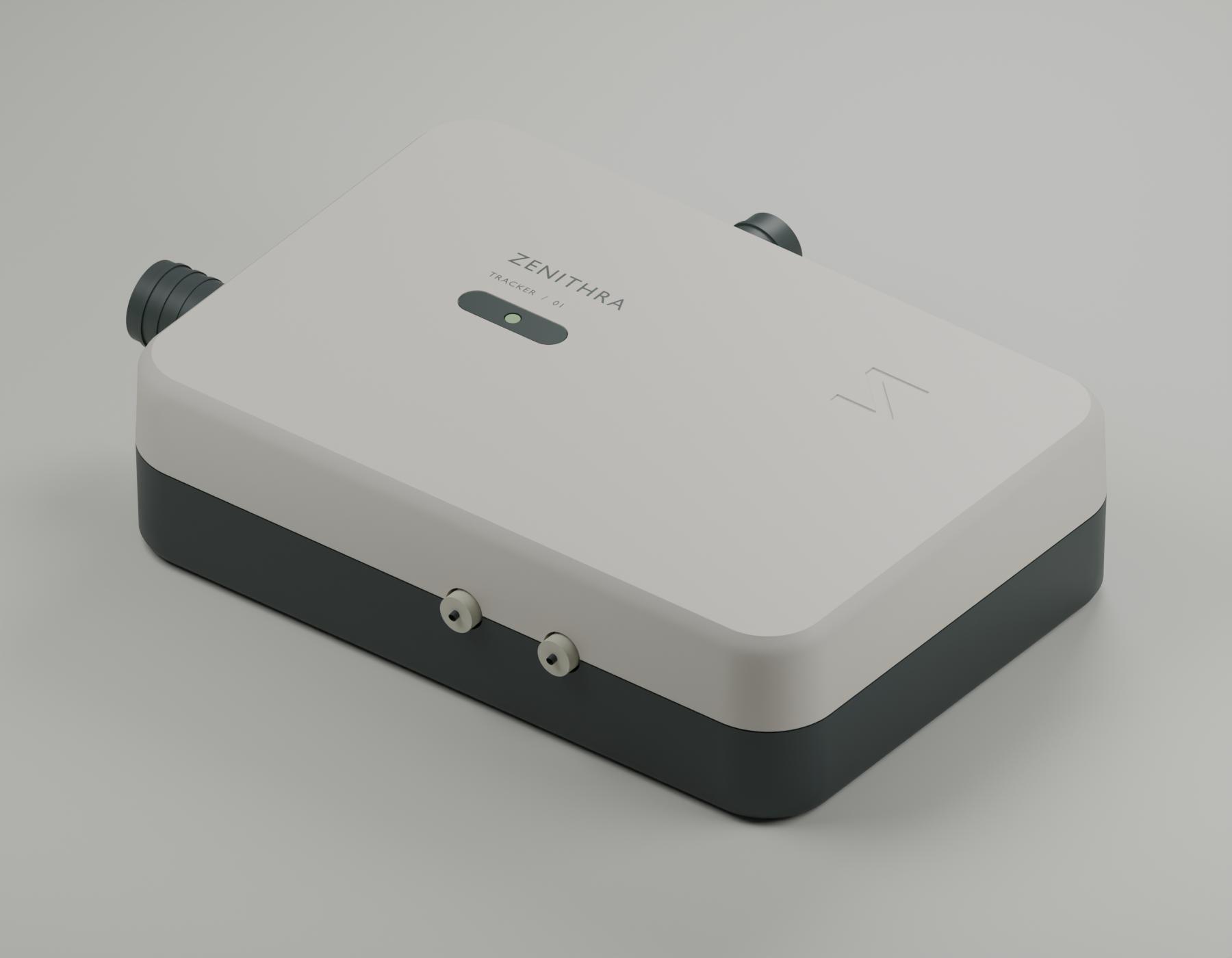
Rounded 12 mm plan corners, a softened crown, recessed branding and replaceable feet. The four closure screws move underneath, leaving the top uninterrupted.
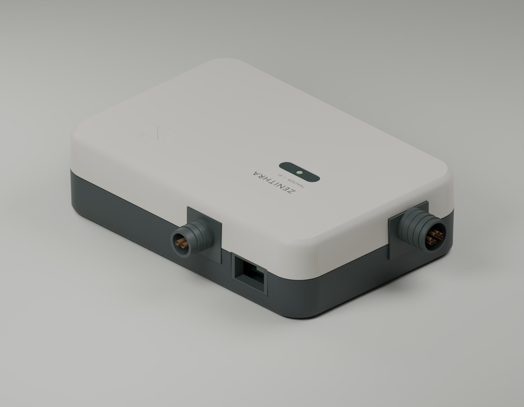
Separate flexible entry inserts, internal tie anchors, recessed USB access and an optional screw-on mounting plate. The antenna bulkheads remain accessible.
The upper shell lifts away. The PCB stays on its original mounts; the protected battery has its own saddles and removable insulating straps.
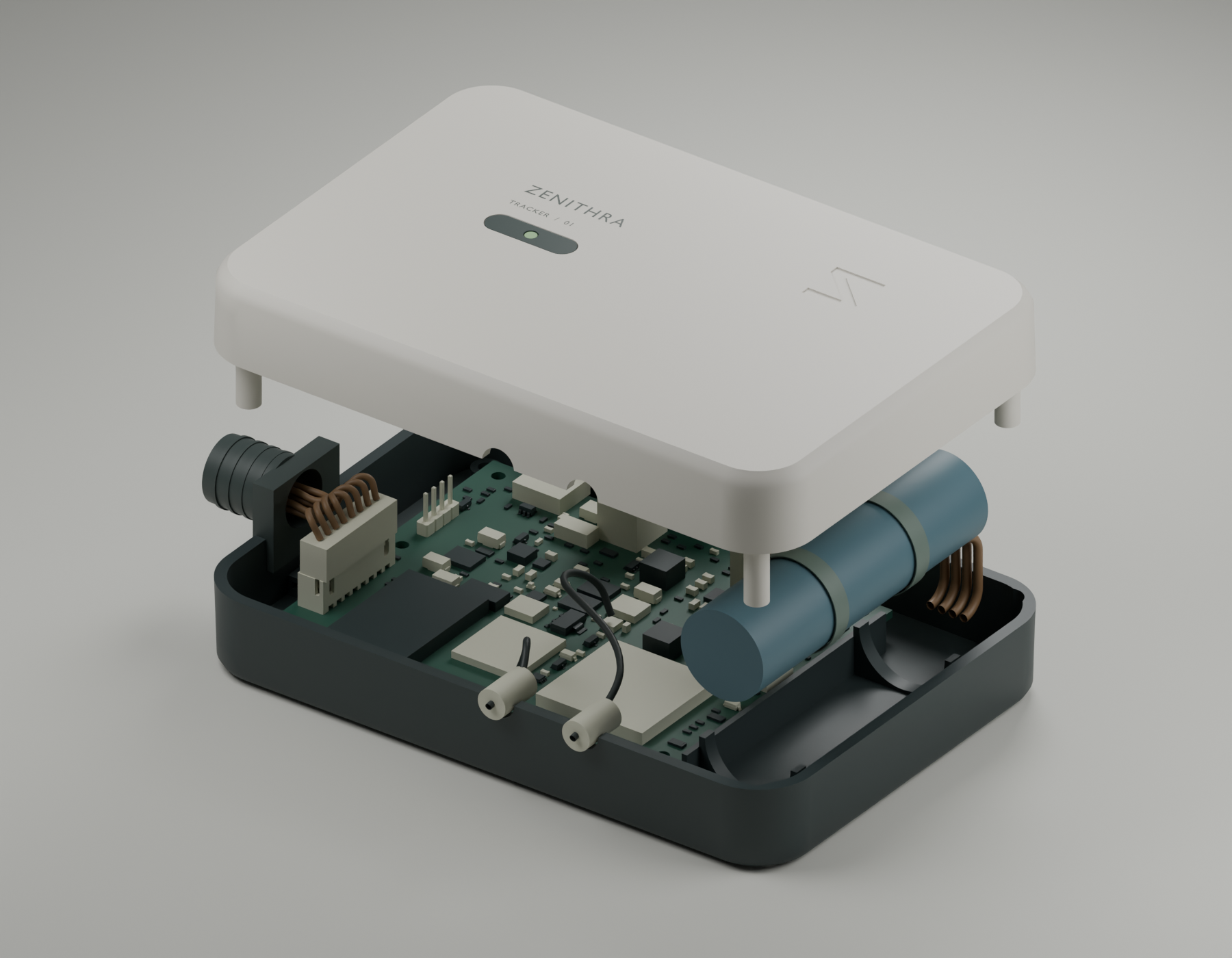
Solid intersections, battery growth, shell registration, USB insertion and lid-removal paths. Harness H1 adds compatible wire diameters, separated battery routes and controlled bend geometry. These checks do not establish drop resistance, sealing, thermal or RF performance.
Build, assemble and test the complete product ↗
Mechanical H is a design-validation revision using unchanged Rev G electronics. It is not the mechanical package currently submitted to JLCPCB. Mold-tool approval and physical qualification remain open; no ingress rating is claimed.
Follow the signal from sensor to software. Choose a subsystem to inspect its components, operating limits and design intent.
| Reference | Part | Subsystem | Value |
|---|
Design register includes test contacts and DNP references. The assembly package contains 169 fitted placements / 70 BOM lines.
Change a signal. Lose the network. Pull the power. Watch admission, output protection and telemetry react.
The browser twin is a behavioral model. Native replay executes the actual C++ protection headers against this session.
Rotate a virtual sensor frame to explore gravity projections, then inspect each harness cavity. Orientation is illustrative; the real firmware uses acceleration magnitude and angular speed for motion detection.
Static rotation alone keeps acceleration magnitude near 1 g. This does not estimate position or prove IMU accuracy.
Cavity labels come from the Rev G wire list. This diagram is logical, not a mating-face orientation drawing. Confirm connector keying before wiring.
Explore how assumed rail impedance, converter efficiency and transmit duty affect the design. These are uncalibrated engineering bounds, not measured performance.
0.1 → 2 A pulse, 100 ms duration. Fixed effective source resistance; no switching-loop model.
Battery: I = 2P / (V + √(V² − 4RP)); SYS = V − IR. Rail: Vmin = Vdc,min − Ipeak × Reffective. Thermal: T(t) = Tamb + Ploss × θ × (1 − e−t/(θC)).
Rev G envelope: 2 A peaks ≤100 ms, ≤20% duty; effective rail resistance ≤0.15 Ω. Efficiencies, hot resistance and thermal parameters require measurements. The 3.5 A switch-current reference applies at the datasheet test point, not a guaranteed hot/low-voltage limit. No FEA, stability, EMI or battery electrochemistry result is implied.
Runs the repository’s Python model on the demo server.
The Rev G baseline below predates Mechanical H. Historical engineering checks, freshly executed host tests and physical acceptance are different kinds of evidence. They stay separate here.
Supplier DFM and assembly alignment findings remain unresolved in the captured Rev G evidence. No commercial release is claimed.
The ESP32-S3 exposes a small application boundary. Read a snapshot, return desired outputs, and keep protection in control.
Outputs application(const Snapshot& s) {
  // true sinks current to ground.
  // Protection can veto these requests.
  return {
    s.din1 && s.ain1 > 6.0f,
    s.moving
  };
}
The actual default firmware returns both outputs OFF. Demo rules do not flash or modify a device.
Connect a browser-supported serial device emitting newline-delimited JSON. Incoming records are shown verbatim as device data, separately from the synthetic twin. No commands or firmware are sent.
No physical tracker connected.
Waiting for a user-selected serial device at 115200 baud.Chrome/Edge desktop with Web Serial, on localhost or HTTPS. A compatible device and JSON-emitting firmware are required. Device readings are not calibrated acceptance results.
Rev G engineering demonstrator · India deployment target · Protected installations